
News Center
Ideas and Insights for Better Living
Folding Container Houses work by rotating connected floor, wall, or roof panels from a compact transport configuration into a deployed building. Hinges guide that movement; engineered locks, connections, bracing, and foundations establish the load path after deployment. Seals close the moving joints, but their performance depends on panel alignment and controlled compression.
A unit can unfold smoothly yet develop sticking doors, leaking corners, or unstable connections once installed. These symptoms may indicate uneven supports, incomplete locking, or joint movement under load. The first evaluation question is therefore not simply whether the unit opens, but whether its deployed geometry, structural connections, and weather seals remain within specified tolerances.
Separate the unfolding mechanism from the deployed structure
Layouts vary. Some units lower floor extensions before raising walls; others use linked panels that move together. The deployment drawings should identify each rotation axis, temporary support point, lifting arrangement, and final connection. A folding unit is not necessarily a modified freight container, so its appearance alone establishes neither transport certification nor building suitability.
Do not assume that a hinge carries the building’s service loads. In some designs, hinges remain structural connections; in others, bearing seats, bolts, locking pins, or braces take over after deployment. Drawings should make that distinction explicit, including how loads cross every folding interface.
Hinges: alignment matters as much as strength
Binding during deployment can arise from misaligned hinge axes, distorted panels, debris, or differential support settlement. Forcing the mechanism can damage pins, attachment plates, welds, or surrounding panel framing without correcting the underlying problem.
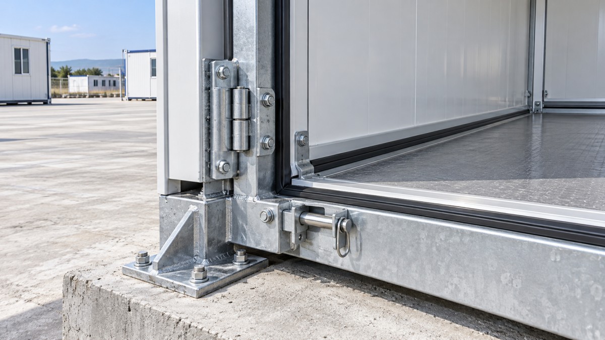
Assess the complete hinge assembly rather than pin diameter alone. Relevant details include pin retention, bearing surfaces, attachment to the primary frame, corrosion protection, lubrication requirements, and access for replacement. Where repeated relocation is intended, request evidence addressing wear and increasing joint clearance over the expected deployment cycles.
- During movement: Verify the specified lifting and temporary support sequence. Panels must not swing freely or overload partially connected components.
- At full extension: Check whether bearing surfaces seat correctly and locking holes align without improvised forcing.
- After locking: Confirm that retainers are fitted and that allowable clearance is defined. Unspecified looseness is not a substitute for a designed movement allowance.
A joint section is particularly useful here: it should show the hinge axis, deployed bearing contact, locking hardware, and seal position together.
Weather resistance depends on the closed joint
A gasket seals only when mating surfaces produce the intended compression along the entire joint. Too little compression leaves leakage paths; excessive compression can damage the gasket, increase closure forces, or accelerate permanent deformation. Compression limits should come from the selected seal’s technical data and the assembly design, not a universal percentage.
Corners, hinge interruptions, and transitions between roof and wall joints deserve close attention. These locations can break seal continuity even when the straight sections look satisfactory. Check gasket splices, retention grooves, fastener penetrations, and whether folding causes the seal to roll, scrape, or become trapped.
Exposed joints benefit from details that shed water before it reaches the primary seal. Overlaps, flashings, drainage channels, and secondary sealing layers may be appropriate, depending on the geometry. Field-applied sealant should not conceal an unexplained gap or replace a specified structural connection.
Water resistance should be assessed in the deployed configuration. Request test conditions, pressure differences, joint details, and acceptance criteria. A material datasheet cannot demonstrate the performance of the assembled enclosure, particularly after repeated folding or structural movement.
Trace loads all the way to the ground
Structural stability requires a continuous path for gravity loads, wind pressure and suction, and other applicable site actions. Roof loads must reach supporting walls or frames; lateral loads need an identified resisting system; uplift must pass through deployed connections and anchors into the foundation.
Wall panels should not be counted as bracing unless their connections and panel construction are designed for that role. Similarly, locks that position panels are not automatically adequate for wind uplift or frame racking.
Review calculations for the actual site, occupancy, support arrangement, and openings. Large door or window openings can interrupt bracing, while added canopies or equipment introduce loads absent from the original design. Connection checks should address applicable failure modes such as pin shear, plate bearing, fastener withdrawal, weld failure, and local frame deformation.
Serviceability also matters: deflection that does not threaten collapse may still impair doors or unload a weather seal. Ask whether calculated movement is compatible with enclosure tolerances.
Acceptance evidence and installation checks
Building-code requirements depend on jurisdiction and intended use. Request a stated design basis, applicable load combinations, connection details, and supporting calculations reviewed as required locally. Enclosure testing should identify the tested configuration and whether it represents the supplied joint design.
Before deployment, verify foundation levels and support locations against the installation drawings. Follow the specified sequence for unfolding, temporary restraint, locking, bracing, and anchoring; some restraints may be required before panels move. Keep personnel clear of suspended panels and pinch points.
Final acceptance should record panel alignment, locking engagement, anchor installation, seal continuity, and operation of doors and windows. When joints cannot close within tolerance, stop and establish whether the cause is support geometry, damaged hardware, or assembly error. Pulling panels into place with extra fasteners can introduce unverified stresses and leave the original defect unresolved.
Navigation
Send Us A Message
Drop a Message